Full wave bridge rectifier Rectifier circuit diagram Rectifier wave circuit diagram transformer working bridge ac dc half ckt applications pcb diodes basics converting shown
Full Wave Bridge Rectifier Operation - Engineering Tutorial
Full wave bridge rectifier operation
Full wave bridge rectifier ckt diagram
Rectifier wave bridge operation half animation working input cycle current positive forward during gif diodes reverse biased d3 d4 d1 .
.
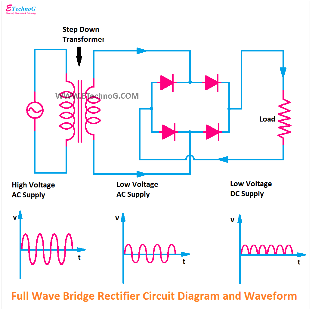
![Rectifier Circuit Diagram | Half Wave, Full Wave, Bridge - ETechnoG](https://1.bp.blogspot.com/-uzWX38U8Hjs/YO60pnoF8UI/AAAAAAAABM8/otQyNJpK8PIUk9vmeOwTroo0cMf9xL06ACLcBGAsYHQ/s16000/Full%2BWave%2BBridge%2BRectifier%2BCircuit%2BDiagram.png)
![Full Wave Bridge Rectifier Operation - Engineering Tutorial](https://i2.wp.com/engineeringtutorial.com/wp-content/uploads/2016/07/engineeringtutorial.com_full-wave-bridge-rectifier-operation.gif)
![Full Wave Bridge Rectifier Ckt Diagram - PCB Designs](https://i2.wp.com/www.electronicsforu.com/wp-contents/uploads/2017/08/full-wave-rectifier-circuit.png)
![Full Wave Bridge Rectifier - its Operation, Advantages & Disadvantages](https://i2.wp.com/circuitglobe.com/wp-content/uploads/2015/12/FULL-WAVE-BRIDGE-RECTIFIER-FIG-5-compressor.jpg)